Now that our topology lines had been finished I could now start working on these lines in 3Ds Max, but before I considered drawing lines I had to ensure I had reference planes made. For this I opended up 3Ds Max and went to standard primatives > plane, and drew a rectangle in the perspective view, making sure that it was behind the halfway line and to the side of the halfway line, so that when I created my model it would be infront. Next I went to the modifier and changed the segments length and width to 1.
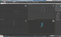
This created a nice plane for which I could display my topology. In order to get my topology to show on my plane I had to first insert it using the material editor. In here, making sure I had selected an empty modifier, under the Blinn Basic Parameter I selected the small grey box next to diffuse, then clicked bitmap. This would allow me to select a picture/ file.
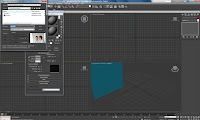
Now that I had selected my topology.psd file I had to make sure that it was visible. When first opened the plane was a grey rectangle. This told me that an image was present but not viewable. To allow me to see my topology I clicked show standard mapping in viewport. This then showed my face/ topology, however it was squashed so clicking on the plane and going to the modifier panel I introduced the use of a UVW mapping modifier from the dropdown box. This would allow me to resize and move my image within the plane without editing the size of the plane itself.
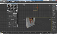
Using the UVW mapping filter I scrolled to the bottom and used a function called bitmap fit. I then selected the my topology.psd file again. This time my image was no longer squashed and was at a size that resembled the image I had created in photoshop.
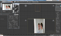
Next to the UVW mapping filter is a + and by clicking this provides another filter called gizmo. Using this allowed me to move my image within my plane without moving the plane itself. Once I had my face profile lined up, I edited the size of my plane by clicking on the plane from the modifier panel and resized so I had nice edges around my face.
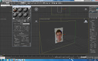
If I was to try modelling my face now it would be hard to distinguish the lines to follow from my topology as the image is quite dark. To make it brighter, in the material editor I used the goto parent function and this brought me back to the child level. Here I changed the self-illumination in the Blinn Basic Parameters section from 0 color to 100. This is displayed in the next two images...
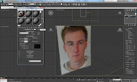
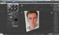
Now that I could see my face and topology lines more clearly I had to then produce my side on profile. To do this I clicked on my plane and then selected the rotation tool from the top toolbar and held down shift. By doing this and dragging the x axis made a copy. I then placed the plane to the side of my original plane.
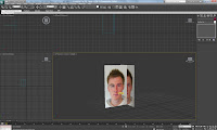
Once I was happy with the positioning I had to use gizmo again to move my picture so that I could see a side on view within my plane. I then had to use the 'z' alignment tab to make sure that my profile was facing the correct way.
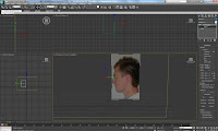 I then had to use the 'z' alignment tab to make sure that my profile was facing the correct way. I also made the plane bigger so that my whole profile could be seen.
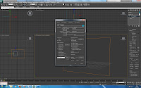
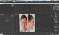 Once I was happy with both the location and size of my planes, I froze them by using right click, object properties and selecting freeze under the interactivity filter. This would freeze the selection so that my planes and gizmo would not move position. The last thing I had to do though was to unselect show frozen in gray, from the display properties. This would allow me to see my plane as my picture and not a grey solid plane.
No comments:
Post a Comment