Now that my reference planes were made and set up, the next part was to finally start working in 3Ds Max making the lines following my topology. The first stage was to change the layout from 4 views to 2. I selected the front view and left view. (This later changes to the right as I done my topology on my right hand side.)
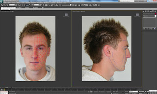
Next was to work on my front view so I could follow my topology lines easier. To get just the front view and zoomed in I clicked Maximize Viewport Toggle which is in the bottom right corner of the workspace area.
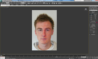
I then began constructing my lines following my topology, to do this I went to the splines modifier and selected line, ensuring that both initial and drag type had corner selected. I also made sure that I had both angle snap toggle and snap toggles on, this would allow me to connect each line to another. By simply following my topology lines I created the 4 sided shapes and linked them thanks to the snap toggle.
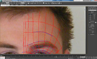
To make sure that I could get the correct vertex to connect to I went into the grid and snap settings and selected vertex. Also in this window I went to the options and changed the settings so that when I had closer vertices to pick that I selected the correct one.
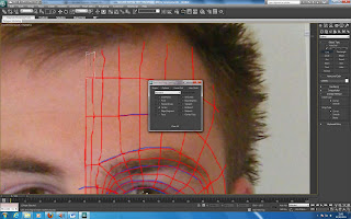
Following my topology lines I first started with the forehead and followed my lines round towards the eye.
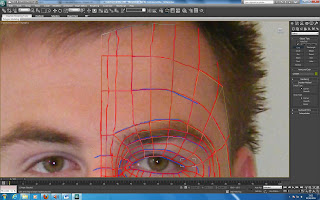
I continued working around the eye and down the nose ensuring that the vertices connected and that I had not missed a section.
The next stage was to use the lines I had constructed to create my face be converted into a editable poly. This would allow me to edit the mesh and give it shape and make it 3D.
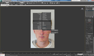
Once this had been done you could see if any gaps appeared from missed line connections. If there was this could be added by clicking off the edit poly and clicking into the spline tool again and filling in the gaps. This is how my face looked once it was converted to an editable poly...
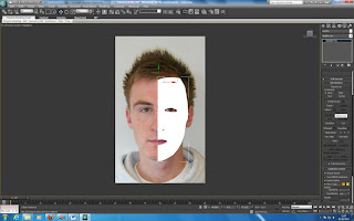
Next I put edged faces on to show how my lines looked and would make for easier editing. This was done by clicking on the wireframe setting and changing it to edged faces. This is how it looked...
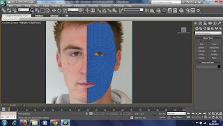
Now that I could see my edges, the next stage was to connect all my verices together so that when I moved a cetain vertex it would move as one and not move just an individual vertex without it being connected. This would mean I would have a gap and not be a whole. To connect all my vertices I highlighted them all by dragging across my newly created layer an under the edit vertices tab in editable poly I clicked the rectange shape next to weld. I then reduced the threshold to 0, next I changed it to 0.1 as I wanted it to be as small a value as possible. As shown in the photo it is noticeable that the vertices have dropped significantly ...
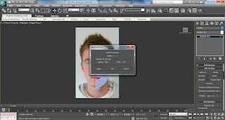
Now that all my vertices were connected I went back to the two views so I could see my side view. In the front view I selected all the vertices on the left hand side (middle of my face) and in the side view I dragged them out towards the edge of my profile. At this stage I changed my viewport from left to right.
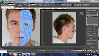
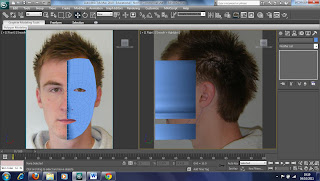
As we could see from the previous picture you can not view the edge of my face so I would not know where I had to place each single vertex. In order to view where I could place them, I right clicked on my poly and selected object properties, and under display properties, selected see-through. Now in the picture below we can see my face through the poly. This allowed me to now move each individual vertex ONLY along the X axis. This is because if I moved it along any other axis it would change in the other views. I moved each vertex to where it should be on the edge of my face...
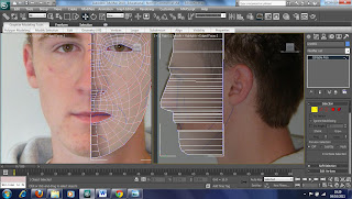
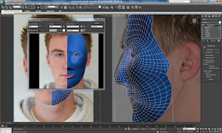
I continued the same process for the other vertices along my face. By following the flow of my face would enable me to get the correct shape so when I looked at different angles you could see that it was becoming 3 dimensional.
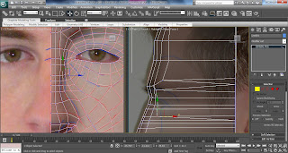
Below is an example to show that I was creating shape. However, my eye was not setup correctly so had to be modified by pulling the vertices in the side view to more realistic positions.


No comments:
Post a Comment