Thursday 20 October 2011

Extending an Organic Model with Primitives

At this stage I was to create the back of my head and connect it to the front of my face. I first opened up my topology.psd file and went to the side profile picture, on my neck I used the blue paint brush again to draw creases and used the red pen to create 4 sided polygons again. I drew this on the back of my head making sure it flowed and went down my neck to my shoulders. The most important part was that I did not draw over my ears as they will be done seperately. I then reloaded my topology in 3Ds Maxx so I could use the newly draw lines as a guide for when I created the back of my head.


Instead of carrying on from the original face and building backwards, a sphere was created using standard primatives > sphere.


Once the sphere was created I then edited the scales of all the axis so that it resembled the size of my head. Once I was happy with the size I reduced the segments so that there was less but along the top had the same number of segments as the top of my face, so that it would be easier to connect them and the face and head would flow.


As you can see from the previous image, the sphere overlaps the front of my face, plus my head is not spherical. The next stage was to delete the appropriate polygons within the sphere, to do this I clicked on my sphere and converted it to an editable poly and clicked on polygons. I then went to the top toolbar, changed rectangular selection region to paint selection region, and window/crossing from outside the square to inside the square. Now I had set these up I dragged from outside the sphere across all the unwanted polygons like a spray can.


With all them polygons selected I deleted them, I then made sure that the vertices would connect with the top of my face. I selected the end vertices of the sphere and ensuring that snap toggle was on I snapped the vertices to the correct vertex on my face. For the end vertex (by my ear side) I went into editable poly, selected the vertex and used soft selection. This gave a more natural curve and made connecting my vertices easier. I then went off soft selection and continued matching up my vertices. Once this was completed I could go about reducing the roundness and amount of polygons again. I then went onto editable poly > edges and selected every other edge on the inside of the sphere. I then under selection press ring, and this highlighted all the edges in that row of polygons around the sphere...


These were then deleted and gave me fewer polygons to work with to make editing simpler and reduce the roundness of my head.


With the basics now set up I could crack on with the creation of the back of my head. I selected certain edges and with the moving tool selected and holding shift I extended out new polygons. I then adjusted them accordingly and made sure that the vertices were snapped together as like earlier.


I continued this process for the remainder of my head and was making sure I connected the correct vertex with the corresponding vertex on my face. This is how it looked when it was connected...


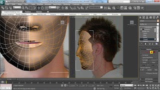
Once I had produced the back of the head, I continued down the neck and part of the shoulder. I used both the front and right angles to adjust the vertices to the postions that they should be according to my plane. Below is how my head and neck was looking from the front view...


I was now happy with how my head was looking so next was to attach my head to my face. To do this I selected my face and went into editable poly. In here under edit geometry I selected the rectangle box next to attach and selected my sphere.


Now that my face had now become one whole mesh, I had to connect my vertices I had snapped earlier with my face mesh. To select them all I again used the same technique from earlier where I deleted the polygons on my sphere. Using the paint spray technique again, I selected all the edged vertices and went down to weld. This welded the vertices together and now when I move a connected vertex it moves as one and not the individual vertex and creating a gap.


Lastly I moved some of the vertices around to create a more natural looking connection between face and back of the head. Below is how my head is looking at this stage...

Refining Organic Models with EditPoly

Once I was happy with the shaping of my face I next moved onto looking at the nose and mouth. I first started on the nose. I created a polygon using the editable poly > polygon > edit geometry > create, I made each vertex connect to an original around the nostril ensuring that snap toggle was on. I then welded the vertices together so that when I extruded the polygon there would not be a gap. I next extruded the polygon using the edit polygon > extrude, and clicking the rectangle next to extrude, next I set the value to -0.4...


For the lips I used a different technique, I clicked on the edges tool in editable poly > edges, and selected the top lip edges. I then clicked on the select and uniform scale button and held down the shift button to create a copy. I then moved the vertices to a position I was happy with, I made sure that the middle part would link up with the other half of my face.


I repeated the same process for the bottom lip and this is the outcome for my lips...


The same can be done for the eyes, I will be looking at this more closely when I come to creating the eyeball for my model.

Mirroring and Subdividing Organic Models

After a few more tweeks to my vertices it was time to mirror my image so it was a full face. To achieve this I used the symmetry filter from the modifier. In this section there is a mirror filter and here is where I mirrored one half of my face to the other. I done this by mirroring the X axis, I then moved the other half by using the move tool til it connected with my original created half.


When looking at my face mirrored and becoming a full face I could see that through the middle it looked like a shark face where it was pointy. To be able to change this I simply went back to editable poly filter, clicked on vertex and made sure I selected the show end result button. This would enable me to edit my right side and automatically change the left.


Monday 3 October 2011

Using Splines to model a head

Now that my reference planes were made and set up, the next part was to finally start working in 3Ds Max making the lines following my topology. The first stage was to change the layout from 4 views to 2. I selected the front view and left view. (This later changes to the right as I done my topology on my right hand side.)


Next was to work on my front view so I could follow my topology lines easier. To get just the front view and zoomed in I clicked Maximize Viewport Toggle which is in the bottom right corner of the workspace area.


I then began constructing my lines following my topology, to do this I went to the splines modifier and selected line, ensuring that both initial and drag type had corner selected. I also made sure that I had both angle snap toggle and snap toggles on, this would allow me to connect each line to another. By simply following my topology lines I created the 4 sided shapes and linked them thanks to the snap toggle.


To make sure that I could get the correct vertex to connect to I went into the grid and snap settings and selected vertex. Also in this window I went to the options and changed the settings so that when I had closer vertices to pick that I selected the correct one.


Following my topology lines I first started with the forehead and followed my lines round towards the eye.


I continued working around the eye and down the nose ensuring that the vertices connected and that I had not missed a section.


I continued following my topology around my face until I had completed it.


The next stage was to use the lines I had constructed to create my face be converted into a editable poly. This would allow me to edit the mesh and give it shape and make it 3D.


Once this had been done you could see if any gaps appeared from missed line connections. If there was this could be added by clicking off the edit poly and clicking into the spline tool again and filling in the gaps. This is how my face looked once it was converted to an editable poly...


Next I put edged faces on to show how my lines looked and would make for easier editing. This was done by clicking on the wireframe setting and changing it to edged faces. This is how it looked...


Now that I could see my edges, the next stage was to connect all my verices together so that when I moved a cetain vertex it would move as one and not move just an individual vertex without it being connected. This would mean I would have a gap and not be a whole. To connect all my vertices I highlighted them all by dragging across my newly created layer an under the edit vertices tab in editable poly I clicked the rectange shape next to weld. I then reduced the threshold to 0, next I changed it to 0.1 as I wanted it to be as small a value as possible. As shown in the photo it is noticeable that the vertices have dropped significantly ...


Now that all my vertices were connected I went back to the two views so I could see my side view. In the front view I selected all the vertices on the left hand side (middle of my face) and in the side view I dragged them out towards the edge of my profile. At this stage I changed my viewport from left to right.


As we could see from the previous picture you can not view the edge of my face so I would not know where I had to place each single vertex. In order to view where I could place them, I right clicked on my poly and selected object properties, and under display properties, selected see-through. Now in the picture below we can see my face through the poly. This allowed me to now move each individual vertex ONLY along the X axis. This is because if I moved it along any other axis it would change in the other views. I moved each vertex to where it should be on the edge of my face...


I continued the same process for the other vertices along my face. By following the flow of my face would enable me to get the correct shape so when I looked at different angles you could see that it was becoming 3 dimensional.


Below is an example to show that I was creating shape. However, my eye was not setup correctly so had to be modified by pulling the vertices in the side view to more realistic positions.


Once I was happy with the outcome I produced a quick render and this is how it looked...

Reference Planes

Now that our topology lines had been finished I could now start working on these lines in 3Ds Max, but before I considered drawing lines I had to ensure I had reference planes made. For this I opended up 3Ds Max and went to standard primatives > plane, and drew a rectangle in the perspective view, making sure that it was behind the halfway line and to the side of the halfway line, so that when I created my model it would be infront. Next I went to the modifier and changed the segments length and width to 1.


This created a nice plane for which I could display my topology. In order to get my topology to show on my plane I had to first insert it using the material editor. In here, making sure I had selected an empty modifier, under the Blinn Basic Parameter I selected the small grey box next to diffuse, then clicked bitmap. This would allow me to select a picture/ file.


Now that I had selected my topology.psd file I had to make sure that it was visible. When first opened the plane was a grey rectangle. This told me that an image was present but not viewable. To allow me to see my topology I clicked show standard mapping in viewport. This then showed my face/ topology, however it was squashed so clicking on the plane and going to the modifier panel I introduced the use of a UVW mapping modifier from the dropdown box. This would allow me to resize and move my image within the plane without editing the size of the plane itself.


Using the UVW mapping filter I scrolled to the bottom and used a function called bitmap fit. I then selected the my topology.psd file again. This time my image was no longer squashed and was at a size that resembled the image I had created in photoshop.


Next to the UVW mapping filter is a + and by clicking this provides another filter called gizmo. Using this allowed me to move my image within my plane without moving the plane itself. Once I had my face profile lined up, I edited the size of my plane by clicking on the plane from the modifier panel and resized so I had nice edges around my face.


If I was to try modelling my face now it would be hard to distinguish the lines to follow from my topology as the image is quite dark. To make it brighter, in the material editor I used the goto parent function and this brought me back to the child level. Here I changed the self-illumination in the Blinn Basic Parameters section from 0 color to 100. This is displayed in the next two images...


Now that I could see my face and topology lines more clearly I had to then produce my side on profile. To do this I clicked on my plane and then selected the rotation tool from the top toolbar and held down shift. By doing this and dragging the x axis made a copy. I then placed the plane to the side of my original plane.


Once I was happy with the positioning I had to use gizmo again to move my picture so that I could see a side on view within my plane. I then had to use the 'z' alignment tab to make sure that my profile was facing the correct way.

I then had to use the 'z' alignment tab to make sure that my profile was facing the correct way. I also made the plane bigger so that my whole profile could be seen.

Once I was happy with both the location and size of my planes, I froze them by using right click, object properties and selecting freeze under the interactivity filter. This would freeze the selection so that my planes and gizmo would not move position. The last thing I had to do though was to unselect show frozen in gray, from the display properties. This would allow me to see my plane as my picture and not a grey solid plane.